Geogrid for Load Support and Soil Stabilization
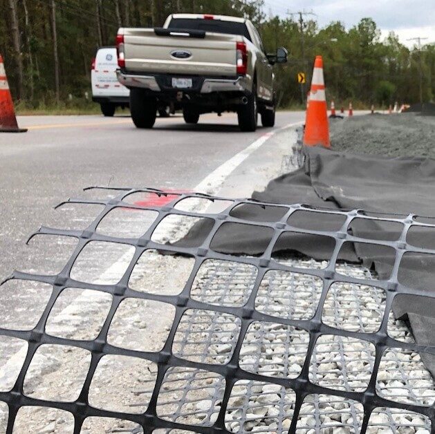
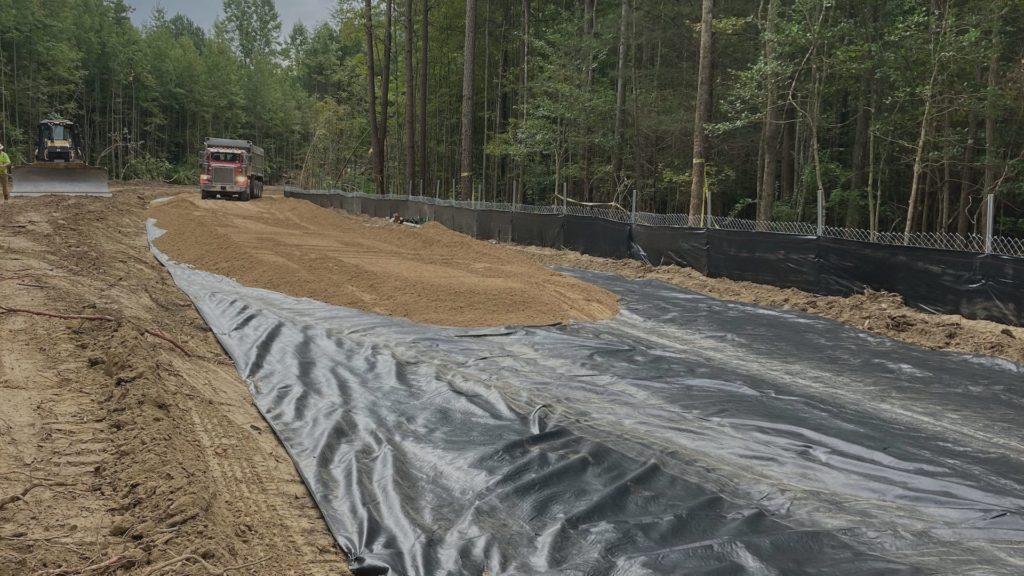
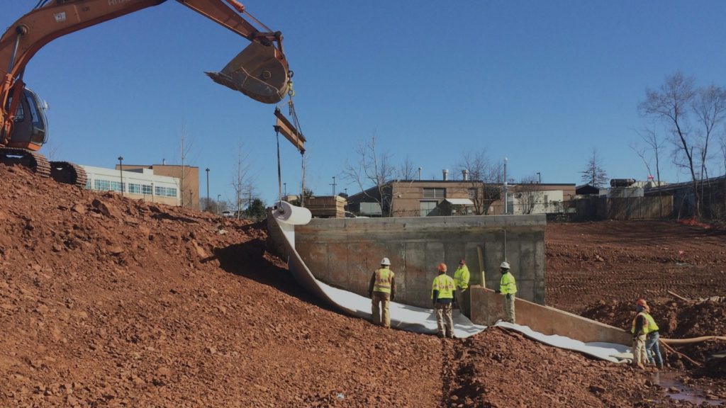
Geogrids stabilize extremely poor soils and support heavy loads. These geosynthetics are categorized by their high tensile strength and are often specified to support haul roads, highway overpasses, high traffic roadways and bridges.
Types of Geogrid
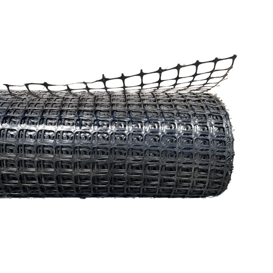
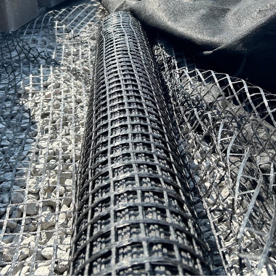
Bi-Axial Geogrids are simple-to-install, high strength geotextiles that stabilize subgrade. When installed properly, this grid reduces the thickness of the aggregate base by confining soil and stone particles.
Confinement prevents lateral shearing which allows the load to spread over a broader plane, ultimately decreasing the pressure applied to the subgrade level.
Bi-axial geogrids have a drawn open aperture that allows the soil or aggregate to fill the space between the ribs to reinforce support for the subgrade. To prevent contamination between aggregate and soil, install bi-axial grids with a nonwoven geotextile fabric.
| Technical Characteristics | BX1100 MD Values1 | BX1100 XMD Values1 | BX1200 MD Values1 | BX1200 XMD Values1 |
|---|---|---|---|---|
| Aperture Dimensions2 | 27 mm (1.06 in) | 37 mm (1.45 in) | 28 mm (1.10 in) | 38 mm (1.49 in) |
| Minimum Rib Thickness2 | 0.76 mm (0.03 in) | 0.76 mm (0.03 in) | 1.27 mm (0.05 in) | 1.27 mm (0.05 in) |
| Tensile Strength at 2% Strain3 | 4.1 kN/m (280 lb/ft) | 6.6 kN/m (450 lb/ft) | 6.0 kN/m (410 lb/ft) | 9.0 kN/m (620 lb/ft) |
| Tensile Strength at 5% Strain3 | 8.5 kN/m (580 lb/ft) | 13.4 kN/m (920 lb/ft) | 11.8 kN/m (810 lb/ft) | 19.6 kN/m (1,340 lb/ft) |
| Ultimate Tensile Strength3 | 12.4 kN/m (850 lb/ft) | 19.0 kN/m (1300 lb/ft) | 19.2 kN/m (1,310 lb/ft) | 28.8 kN/m (1,970 lb/ft) |
Notes
1. Unless indicated otherwise, the values shown are the minimum average roll value determined in accordance with ASTM D4759-02.
2. Nominal dimensions.
3. Tensile Strength is determined in accordance with ASTM D6637-10 Method A.
| Structural Integrity | BX1100 | BX1200 |
|---|---|---|
| Junction Efficiency4 | 93% | 93% |
| Flexural Stiffness5 | 350,000 mg-cm | 750,000 mg-cm |
| Aperture Stability6 | 0.32 m-N/deg | 0.65 m-N/deg |
Notes
4. Load transfer capability determined in accordance with ASTM D7737-11.
5. Resistance to bending force determined in accordance with ASTM D7748-12, using specimens of width two ribs wide, with transverse ribs cut flush with exterior edges of longitudinal ribs, and of length sufficiebtly long to enble measurement of the overhang dimension.
6. Resistance to in-plane rotational movement measured by applying a 20 kg-cm (2 m-N) moment to the central junction of a 9-IN x 90IN specimen restrained at its perimeter in accordance with US Army Corps of Engineers Methodology for measurement of torsional rigidity.
| Durability | BX1100 | BX1200 |
|---|---|---|
| Resistance to Installation Damage7 | 95% SC / 93% SW / 90% GP | 95% SC / 93% SW / 90% GP |
| Resistance to Long Term Damage8 | 100% | 100% |
| Resistance to UV Damage9 | 100% | 100% |
7. Resistance to loss of load capacity or structural integrity when subjected to mechanical installation stress on clayey sand (SC), well-graded sand (SW), and crushed stone classified as poorly graded gravel (GP). The geogrid shall be sampled in accordance with ASTM D5818-06 and load capacity shall be determined in accordance with ASTM D6637.
8. Resistance to loss of load capacity or structural integrity when subjected to chemically aggressive environments in accordance with EPA 9090 immersion testing.
9. Resistance to loss of load capacity or structural integrity when subjected to ultraviolet light and aggressive weathering in accordance with ASTM D4355-05.
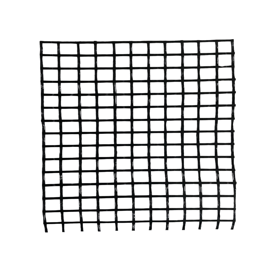
SF Series Uniaxial Geogrids are composed of high molecular weight, high tenacity multifilament polyester yarns that are woven into a stable network placed under tension. The high strength polyester yarns are coated with a PVC material.
These geogrids have unparalleled strength in one direction. This one-directional strength makes it purposeful in tie back applications for MSE walls, berms, and other geosynthetic structures.
SF Series Geogrids are proudly made in America!
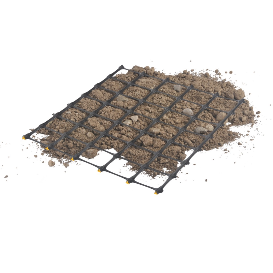
Triplanar Geogrid is manufactured from a unique extrusion process resulting from a perforated polypropylene sheet that is specifically shaped to create a triplanar reinforcing structure. This process produces a large concave shaped rib to better trap aggregate materials by restricting horizontal movement of stone and preventing displacement. Higher profile ribs and junctions improve interlock and stress distribution, thereby reducing rutting and aggregate base thickness.
| Physical Properties | 3D-LT Values1 | 3D-T Values1 | 3D-HT Values1 | 3D-XL Values1 |
|---|---|---|---|---|
| Rib Pitch – MD/XMD2 | 33 mm (1.30 in) / 33 mm (1.30 in) | 32 mm (1.26 in) / 32 mm (1.26 in) | 32 mm (1.26 in) / 32 mm (1.26 in) | 60 mm (2.40 in) / 60 mm (2.40 in) |
| Mid-Rib Depth – MD/XMD2 | 3.0 mm (0.12 in) / 1.0 mm (0.04 in) | 3.3 mm (0.13 in) / 1.2 mm (0.05 in) | 3.5 mm (0.14 in) / 1.2 mm (0.05 in) | 3.0 mm (0.12 in) / 1.3 mm (0.5 in) |
| Mid-Rib Width – MD/XMD2 | 3.3 mm (0.13 in) / 2.0 mm (0.08 in) | 3.5 mm (0.14 in) / 2.0 mm (0.08 in) | 3.7 mm (0.15 in) / 2.0 mm (0.08 in) | 3.8 mm (0.15 in) / 4.8 mm (0.19 in) |
| Rib Shape – MD/XMD | Inverted T Beam / Rectangular | Inverted T Beam / Rectangular | Inverted T Beam / Rectangular | Rectangular |
1. Unless indicated otherwise, values shown are minimum average roll values determined in accordance with ASTM D4759-11.
2. Nominal dimensions.
| Structural Integrity | 3D-LT Values | 3D-T Values | 3D-HT Values | 3D-XL Values |
|---|---|---|---|---|
| Aperture Stability3 | 0.30 N-m/deg | 1.0 N-m/deg | 1.2 N-m/deg | 1.4 N-m/deg |
| Flexural Stiffness4 | 1,200,000 mg-cm | 2,100,000 mg-cm | 2,750,000 mg-cm | 3,000,000 mg-cm |
| Radial Stiffness at 0.5% Strain – MD/XMD5 | 204 kN/m (14,000 lb/ft) | 321 kNm (22,000 lb/ft) | 372 kNm (25,520 lb/ft) | 437 kNm (30,000 lb/ft) |
3. Resistance to in-plane rotational movement measured by applying a 20 kg-cm (2 m-N) moment to the central junction of a 9-IN x 9-IN specimen restrained at its perimeter in accordance with ASTM D7864-15.
4. Resistance to bending force determined in accordance with ASTM D7748-14, using specimens of width two ribs wide, with transverse ribs cut flush with exterior edges of longitudinal ribs, and of length sufficiently long to enable measurement of the overhang dimension.
5. . Radial stiffness is determined from tensile stiffness measured in any in-plane axis from testing in accordance with ASTM D6637-15, tolerance +/-2%.
| Durability | 3D-LT Values | 3D-T Values | 3D-HT Values | 3D-XL Values |
|---|---|---|---|---|
| Resistance to Installation Damage6 | 100% SC / 100% SW / 100% GP | 100% SC / 100% SW / 100% GP | 100% SC / 100% SW / 100% GP | 100% SC / 100% SW / 100% GP |
| Resistance to Long Term Damage7 | 100% | 100% | 100% | 100% |
| Resistance to UV Damage8 | 100% | 100% | 100% | 100% |
| Resistance to UV Damage9 | 100 years | 100 years | 100 years | 100 years |
6. Resistance to loss of load capacity or structural integrity when subjected to mechanical installation stress in clayey sand (SC), well graded sand (SW), and crushed stone classifed as poorly graded gravel (GP). The geogrid shall be sampled in accordance with ASTM D5818-11 and load capacity shall be determined in accordance with ASTM D6637.
7. Resistance to loss of load capacity or structural integrity when subjected to chemically aggressive environments.
8. Resistance to loss of load capacity or structural integrity when subjected to ultraviolet light and aggressive weathering.
9. Test for declared service life up to 100 years of combined aging for Polypropylene Material.


